| Bandmarked | |
| Striped |
| Communications Cables Color Codes |
Background
Telephone wiring in the U.S. is based on pairs of conductors (individual wires) which form an electrical loop. The two conductors of a pair are twisted together so they won't separate and to enhance electrical properties. For decades, the telephone industry has relied on an established method of telling one pair from another. This method involves using 10 basic colors and combining them in a logical sequence to make 25 unique pair combinations. The colors are referred to as "Tip" and "Ring", terms which originate with the old plug-and-cord based switchboards. The plug was a phono jack type with a tip element, an insulating disk, and the shaft, or ring, of the plug. The conductors of the pair were terminated in their respective elements of the plug.
| Tip Colors | Ring Colors |
| White | Blue |
| Red | Orange |
| Black | Green |
| Yellow | Brown |
| Violet | Slate (gray) |
To make 25 different pairs, each tip conductor color is combined with each ring conductor color. The full sequence looks like this:
| Pair | Tip | Ring | Pair | Tip | Ring |
| 1 | White | Blue | 13 | Black | Green |
| 2 | White | Orange | 14 | Black | Brown |
| 3 | White | Green | 15 | Black | Slate |
| 4 | White | Brown | 16 | Yellow | Blue |
| 5 | White | Slate | 17 | Yellow | Orange |
| 6 | Red | Blue | 18 | Yellow | Green |
| 7 | Red | Orange | 19 | Yellow | Brown |
| 8 | Red | Green | 20 | Yellow | Slate |
| 9 | Red | Brown | 21 | Violet | Blue |
| 10 | Red | Slate | 22 | Violet | Orange |
| 11 | Black | Blue | 23 | Violet | Green |
| 12 | Black | Orange | 24 | Violet | Brown |
| 25 | Violet | Slate |
Note: Listing the tip color first is common practice for premises cables and connectivity components. However, for outside plant cables, US standards typically list the ring colors first. It doesn't make a difference; the sequence is still the same. Pair one, for example, has one white conductor and one blue conductor regardless of which you say first.
Using this method an installer can navigate pretty effectively in a 25 pair group of pairs and be able to tell one pair from another. A 25 pair group becomes the basic building block for bigger cables. How do you tell one 25 pair group from another since they both will have the same sequence of pair colors in them? Each 25 pair group, or unit, as they are also called, is loosely bound with colored binders. The binder color sequence is the same as that of the pairs, i.e., the binders for group one are colored White/Blue, for the second group are colored White/Orange, and so on. This system allows up to 600 pair cables (violet/slate binders are never used; 25 pairs x 24 units = 600 pair) to be made. Above 600 pair for all cables, and above 900 pair for cables used in the Bell and GTE systems, it gets more complicated and I'm not going to detail that here.
How does this relate to the residence? This system is not always used for wiring inside the home. Instead, a color code using green, red, black, and yellow is frequently employed. Many questions related to installing a second phone line in a home come down to confusion over mating one color code scheme with another. The table below shows how they relate to each other.
| Pair | Standard Color Code | Alternate Color Code | |
| 1 | Tip | White | Green |
| Ring | Blue | Red | |
| 2 | Tip | White | Black |
| Ring | Orange | Yellow | |
| 3 | Tip | White | White |
| Ring | Green | Blue | |
| 4 | Tip | White | Brown |
| Ring | Brown | Orange | |
Positive Identification
Wiring for premises sometimes employs some method of marking to show which tip conductor belongs with which ring. This is referred to as positive identification and is accomplished using bandmarks or stripes. Typically a large pair count cable used in the Outside Plant (OSP) does not have bandmarks or stripes.
A bandmark is a ring of ink encircling the conductor at regular intervals. A longitudinal stripe is a narrow mark either painted down the length of the conductor or included in the color of the insulation during extrusion.
| Bandmarked | |
| Striped |
In a white/blue pair the white conductor would have blue bandmarks (or a blue stripe) and the blue conductor would have white bandmarks (or a white stripe). Note that in a cable smaller than 6 pairs, it may only be necessary to apply bandmarks or stripes to the tip conductor (all the ring conductors will be a unique color). For premises wiring in Categories 4, 5, and higher, positive identification may not be used at all since more demanding performance requirements dictate more frequent twists per foot and the conductors of a pair stay together better.
The point is, you will probably encounter cables both with bandmarks and stripes and those without them, but the basic color codes are the same.
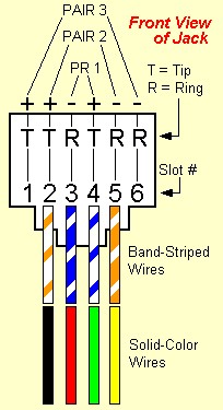
Use the diagram below to translate between the two schemes.
white with blue = green
blue with white = red
white with orange = black
orange with white = yellow

A yellow and blue "jumper" is often used for "cross-connect" between two interface points.
|
|
| ||||||||||||||||||||||||||||||||||||||||||||||||||||||||||||||||||||||||||||||||||||||||||||||||||||||||||||||||||||||||||||||||||||||||||||||||||||||||||||||||||||||||||||||||||||||||||||||||||||||||||||||||||||||||||||||||||||||||||||||||||||||||||||||||
|
|